Modular Mechanical Keyboard Pt. 2
2025-05-31 23:46:07 -0400 EDT
Recap:
Last time on np24.cc:
We designed a modular mechanical keyboard and ordered the parts, in the interim I have received the parts and assembled the keyboard. It’s been several weeks and I’ve been using it daily, so I decided it’s a good time to write a follow-up post about all the things I fucked up…
Unboxing:
Upon getting all the parts from JLC I realized I fucked up the top plate. I accidentally left the soldermask green instead of black so it looks like shit. That’s fine it just drives me insane.
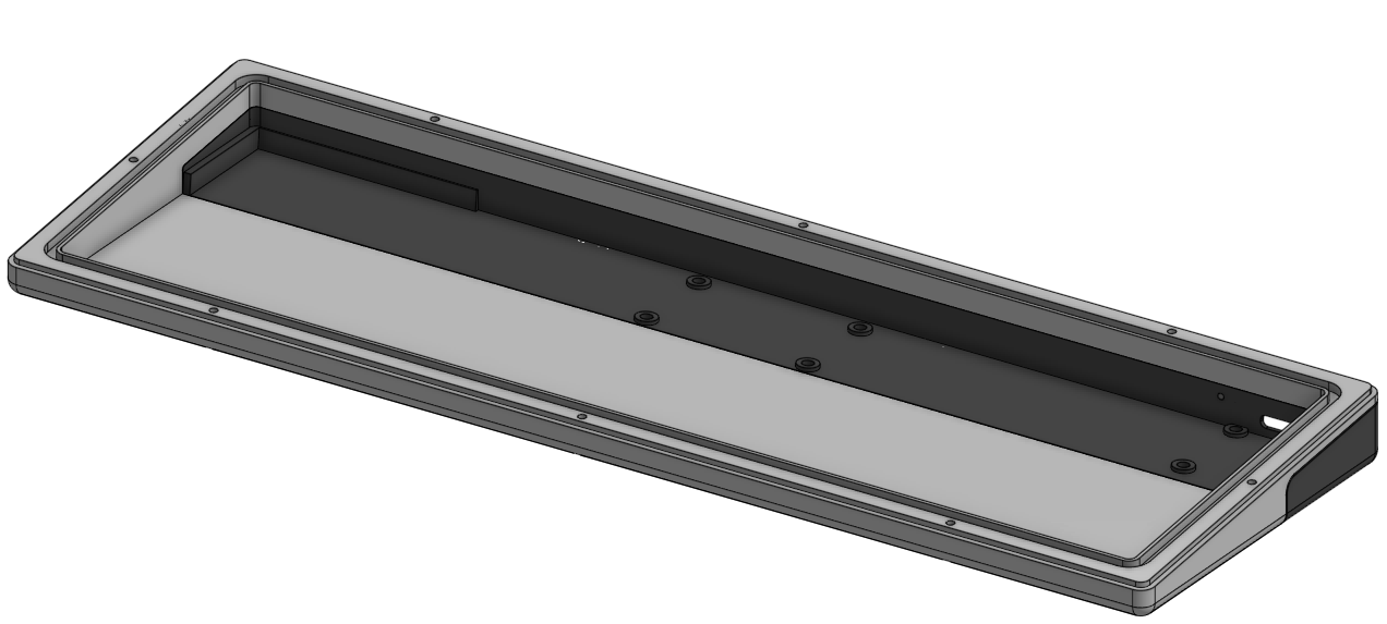
Case:
JLC emailed me telling me the parts were warped and I told them it was fine, they’re just test parts after all right? Well, they’re functional the way they are now but they look and feel like absolute shit and occasionally the pcb holding the switches shifts which feels… unsettling. I also realized I need some more screw holes to keep the whole thing together, even if the plastic wasn’t warped it’s still barely held together. The only other problem is I didn’t add rubber feet, I didn’t think the keyboard would slide around too much and it honestly doesn’t. It does however get scratched to fuck on the bottom by my desk.
Electronics:
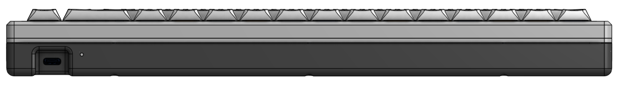
The electronics mostly worked! Upon investigating the firmware a little more closely I realized I don’t need the battery voltage divider, the microcontroller I’m using actually has an internal voltage divider on an adc channel that will directly read from the input voltage to read battery voltage. I ran into a small issue with the 5v power supply for driving the rgb lighting… I underspecced it by a lot. It ran for maybe 30 seconds then died shorting vbat to ground making the keyboard no longer turn on. In my defence I couldn’t find much info online about how much current the LEDs I’m using draw and only recently figured out there’s a calculator online for it. I actually have a coworker who does lighting and pyrotechnics for some events sometimes and she told me about it. A further issue I ran into was ZMK can’t go to sleep and wake up from a keypress… so far this hasn’t been a problem but I can’t get the power light to shut off so I think in the future I should just add a power switch to the keyboard. The final problem I had was the position of the status led, it bleeds throught the hole for the usbc port and looks a little ugly, I can live with it but I want to move the led further away from the port in the future.
Firmware:
The firmware took awhile to get working. First I had to program it, I tried directly flashing a build of ZMK to the board built for a different keyboard with the same micro and it didn’t boot. After some digging I realized typically people flash a bootloader that is then used to flash ZMK over usb, so I resolved to do this. I found a bootloader from adafruit zmk usually is used with on this micro and flashed a version built for another board. It worked! So then I flashed ZMK to the board and it showed up as a keyboard! Great! Now I just needed to write some configuratin files for all my hardware to make it work. After a few hours or so I wrapped my head around configuring ZMK and got a build, I flashed it and it showed up as a keyboard but did absolutely nothing else. I decided I probably fucked up soldering a connector for an FFC cable so I took the board apart and poked at it. The keyboard started working! I reflowed the solder and looked at it under a microscope at work, no visible problems. So I put it back together and it didn’t work again. After about a week of looking at it for a couple hours every night I decided the FFC cable is fine. I resolved to hook my programmer back up and debug the firmware, I found it was hanging up on a function called something like “LS_oscillator_init” which pretty clearly is waiting for the RTC clock to stabilize… Wait I don’t even HAVE an RTC clock… Ok so I found a flag to disable the rtc and recompiled the firmware, flashed it and it worked! Why the fuck it worked when I pressed on the connector is one of the worlds big mysteries. I must’ve induced some noise in something that the micro interpreted as an rtc clock. I still haven’t exactly gotten bluetooth working but honestly I don’t care anymore. I don’t even want bluetooth at this point, I always have it plugged in anyway.
Keycaps:
I found some cheap double shot pbt keycaps on Amazon with an industrial aesthetic. They are yellow, white, and grey and I love them. 10/10 would recommend.
User Experience:
I actually really enjoy using this board, the switches are really nice feeling and the plastic case still sounds quite good. I would like to revise the keyboard to fix the problems I’ve detailed here but I can’t decide if it’s worth it yet.
Modular Mechanical Keyboard
2025-04-13 16:23:00 -0400 EDT
Backstory
Ok so don’t get me wrong, I like mechanical keyboards, but I’m not crazy about them. When I was a kid in high school I remember a few computer labs around the school had these old Dell keyboards that were still membrane, but the keys had a lot of travel and they were generally pleasant to type on. A few of us would always express our excitement when we got to use those over the newer, shittier, lower profile keyboards. I was always vaguely aware that fancy keyboards were a “thing” and there were people out there with a little bit of an obsession with them, but that was the first time I actually cared about them.
In college I decided to buy a cheap Chinese mechanical keyboard with tactile switches off Amazon because the keyboard I was using was dying. I liked that keyboard but the keys were always very rattle-y and it just generally felt low quality. I liked the tactile feel and eventually I decided to just buy a Model M off of eBay.
I really enjoyed the Model M and used it regularly for a few years, but recently I went to a LAN party with a couple coworkers and some friends and one of them definitely is one of those people that are crazy about mechanical keyboards. I tried their keyboard and holy fucking shit it was amazing. It had low profile switches, they weren’t tactile but somehow typing on it still scratched my brain like my tactile keyboards did. I also was shocked by how little play the keys had, they didn’t wobble or clack when you touched them. I had to have something like this.
Goals
Now, naturally, since I don’t know shit about keyboards, I decided to make one from scratch. Since I don’t know shit about these, and I know I’m gonna waste a lot of money, I decided to make it as modular as possible so when I fuck up or decide I don’t like something I can just remake a smaller part of the keyboard.
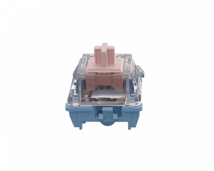
Switches
I started by finding a switch I liked. I watched a fuckton of videos and decided I liked Gateron Melodics (plus, trans they’re trans flag colored which is based AF). For modularity I found some Kailh hot swap sockets. I went to order them and realized I had no idea how many to order because I had no idea what layout I wanted to use.
Keyboard Layout
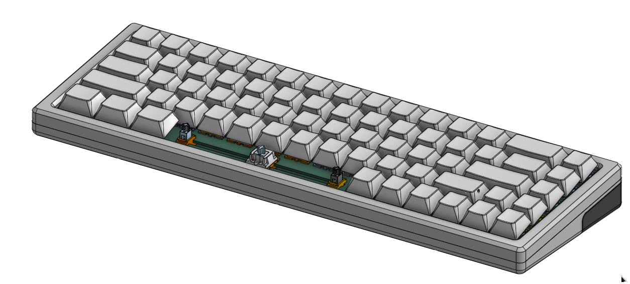
I wanted something small but I wanted it to still be usable, so I looked at some layouts. 40 percent? Imagine not having number keys, pass on that shit… 60 percent? Ehhhhh, I would miss page up and page down… Then I found 68%, IMO it’s the minimum practical keyboard.
Mechanical
Ok so next I needed to figure out the mechanical part, googling around it looks like all aluminum and gasket mount is pretty optimal so I decided to go with that. Oh fuck wait I want it to be wireless, antennas don’t like aluminum… ok so I guess there’ll be some plastic.
Firmware
Next I needed to figure out the electronics… I don’t wanna write all the firmware for this, I knew QMK was a thing so I looked at that. Wireless support on QMK is uh… complicated. Ok so what else is there?
I found a firmware in Rust that supported wireless, upon further inspection it does not support RGB. Why would I build a keyboard with no RGB??? Then I found ZMK. ZMK, from my understanding, exists because people wanted QMK but with actual wireless support. That sounds perfect.
Hardware
Ok, hardware time for real now! The general expected way to build a keyboard with ZMK seems to be to buy a board that you solder switches to and attach an Arduino compatible board to it. I don’t like that, I’d rather just have several boards connected by flat flex cables. Of the micros supported I decided on the NRF52840 because of the amount of IO. I really wanted to layout some RF stuff, so I decided to just buy the chip and not a module.
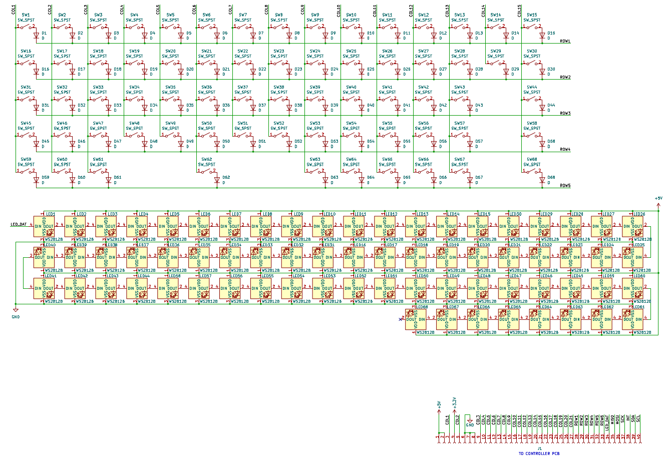
Ok so RGB, I like those addressable LEDs that just pass data through them. It looks like the common solution in that vein for keyboards is the SK6812MINI mounted upside down.
I broke this project up into 3 boards (maybe four if you count the top plate). I have the main key board with the keyswitch sockets and LEDs, a board with the MCU and LiPo charger/regulators, and a board with the USB-C connector and protection IC. I also have a top plate that holds the switches in place.
I made a spreadsheet and threw together some pinouts for the boards and found some appropriately sized FFC connectors from Molex. I also decided to try some low profile connectors from JST I found recently that are specifically meant for battery connections. An overview here is as follows:
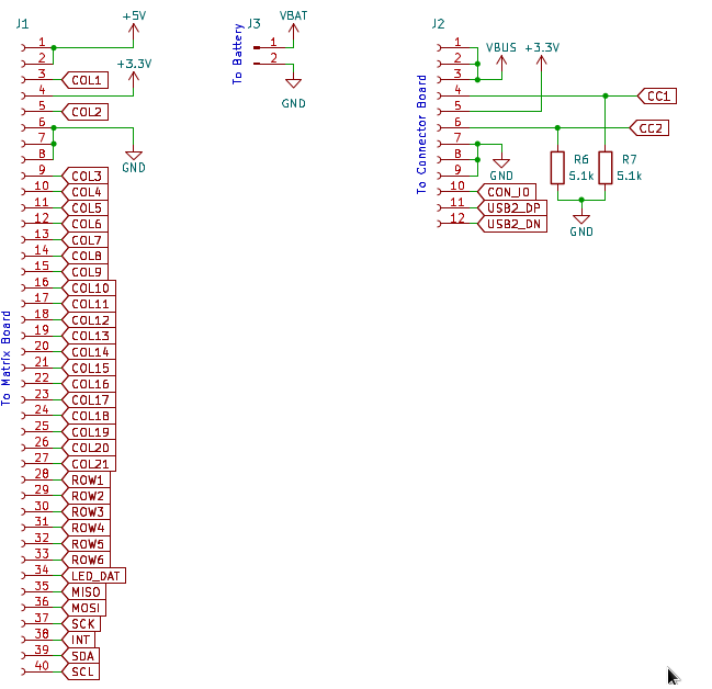
Key board to MCU board - all the lines for a keyboard matrix for a full keyboard, a 5V supply capable of enough current to run the LEDs, a 3.3V supply, a line for addressable LEDs, and lastly SPI and I2C busses for any future shenanigans.
MCU board to connector board - VBUS, a 3.3V supply, the CC lines for USB-C, USB 2 data lines, and an IO for maybe a button or an LED.
A little thing I want to note that I always do when possible is make sure my connector pinouts will not short power to ground when something is plugged in backwards, as well as make sure that any power pins are not next to each other so a short won’t kill the board. I remember watching a Louis Rossmann video when I was in high school where he was complaining about Apple putting power and ground next to each other on the connector for the LCD backlight or something and that always stuck with me.
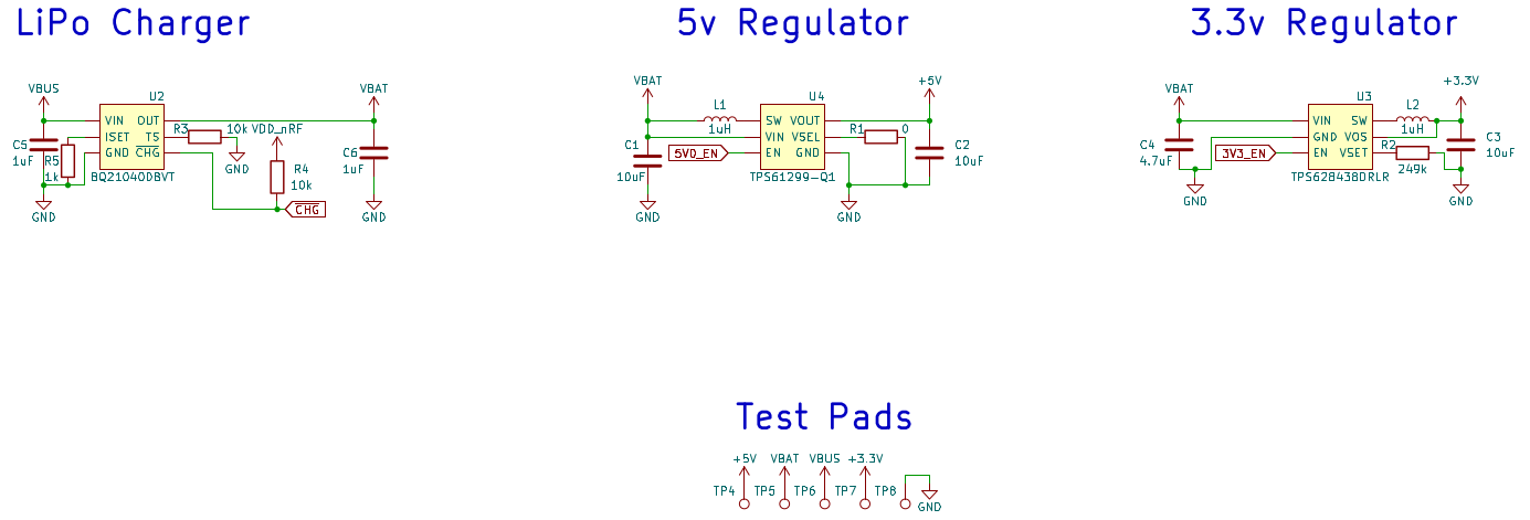
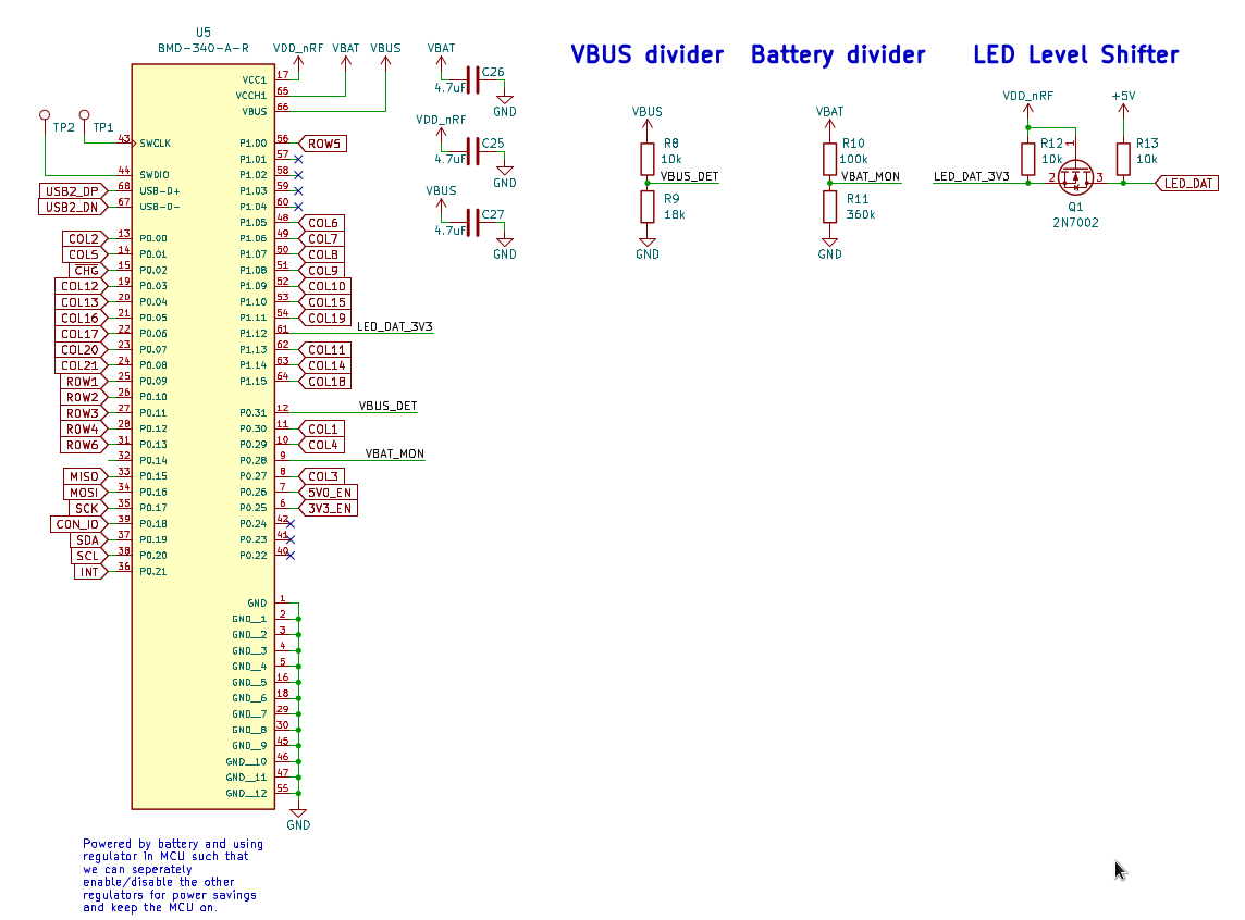
I initially thought I was going to have to use a FET to cut power to the key board when the MCU board was in sleep mode since the MCU would still need power… as it turns out this is unnecessary!! The NRF52840 has a built-in DC/DC converter and I can just feed it VBAT directly and configure this to power the MCU. Then I can just shut the regulators down when the MCU should be asleep. This was one of those moments where I feel like a real engineer and not some t-girl with a CS degree and programmer socks on pretending to be an EE.
I’m getting pretty good at making these IoT-ish devices, this is like the third one this year, so that’s honestly all the interesting stuff that happened during schematic design. Here’s the main parts I used:
5V regulator: TPS61299Q
3.3V regulator: TPS628438
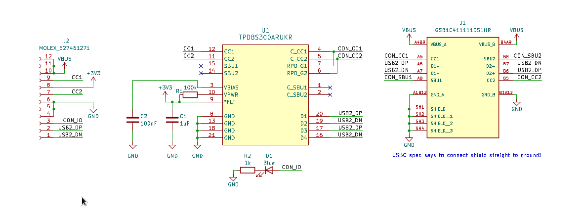
USB-C protection IC: TPD8S300
LiPo charger: BQ21040
and a fuckton of passives and stuff
Without further ado, pretty pictures:
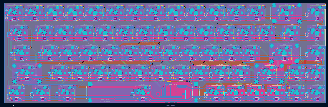
Key Board
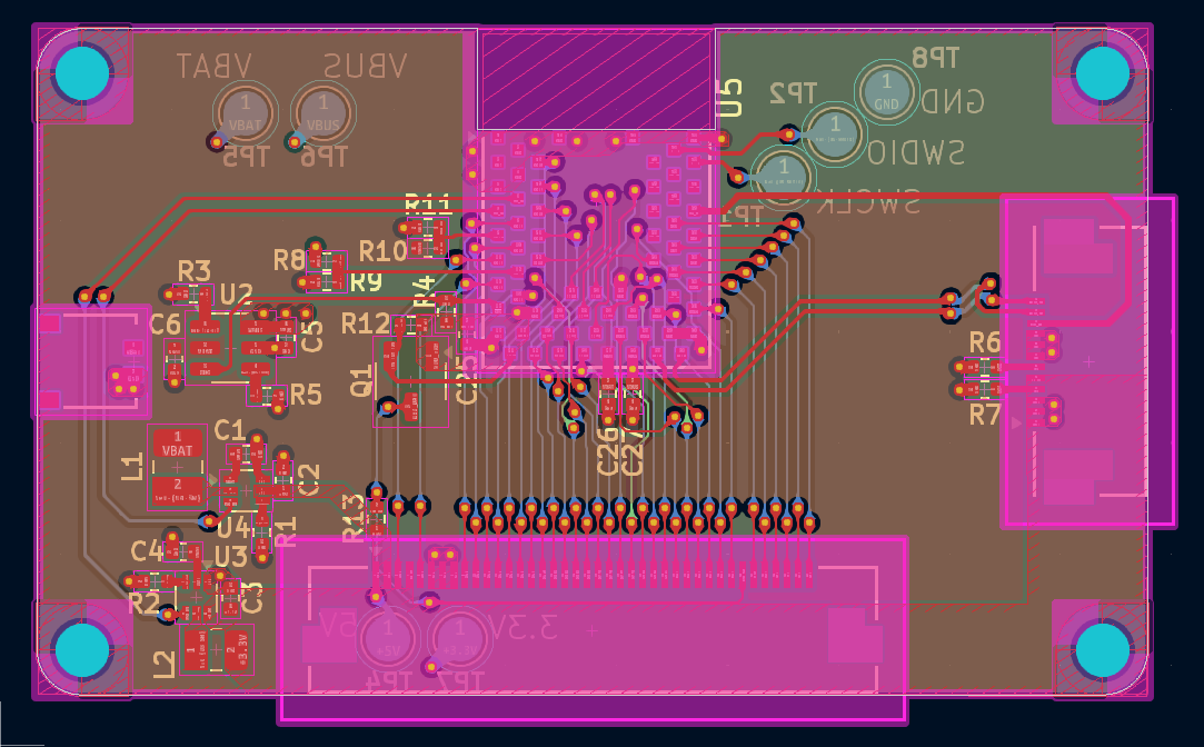
MCU Board
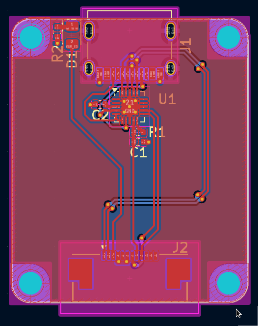
Connector Board
Layout
I’ve always liked doing layout, it’s relaxing. I started with the key board. I used keyboard layout editor to figure out my exact layout then used a KiCad plugin for placement based on that. This was really fucking cool because it made placing all these parts take me only like 45 minutes, I fully expected to spend hours on it. Routing was fairly painful as it tends to be with big key matrices, but it was still pretty easy. My workflow generally starts with placement, goes to routing, then ends with figuring out power planes, so naturally I tend to get bored and end up just using a 4 layer board instead of getting creative enough to make 2 work. I got DAMN CLOSE to doing 2 on this board but still ended up with a 4 layer stackup with power planes in the middle.
Next up: connector board. This was pretty easy but I ended up laying it out 3 times because I hadn’t landed on exact dimensions. I managed to get it done with 2 layers which was nice. Honestly nothing really interesting happened here.
Lastly: MCU board. I actually took a break from layout first to finish up the CAD. I tend to do some rough mechanical, make sure everything fits on the space I allocated for the boards, then finish mechanical before doing all the layout, but the last two boards were simple enough that I just knocked them out. Anyway, I started with the power supplies, generally switching power supplies are pretty easy to route, just keep the current loop as short as possible and if you actually care about EMI don’t put anything important under any inductors. At work I care, here I don’t, so this layout isn’t super great from an EMI perspective. Next I did the MCU, or at least I tried… turns out the package for the NRF52840 that has the number of pins I needed needs some very small vias and via in pad to break out. This is fine but I was feeling cheap and lazy so I scrapped the whole idea of using the chip to try my hand at some RF layout and just found a nice module. I ended up using a BMD-34 series module from u-blox with a built-in antenna. I thought this was gonna be another annoying routing job but it ended up being kinda nice, I did a lot of pin swapping to get the traces to line up with their respective pins on the FFC connector to the key board and it just came out really nice.
Mechanical CAD
I used to use Fusion 360 for all my CAD needs but Autodesk has gradually pissed me off more and more. I switched to FreeCAD for a couple weeks and got frustrated with the amount of crashing I experienced and this was my first project on Onshape. Overall, pretty solid product, being browser based I can use it on Linux and that’s really nice.
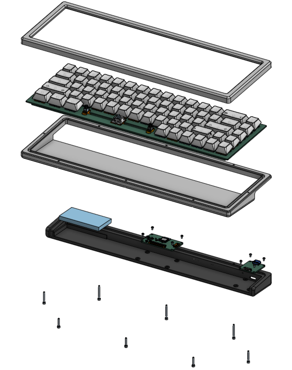
The overall mechanical design has 3 parts: the top case, the bottom case, and a plastic piece that holds the electronics. The idea here is that most of the device can be made of CNC’d aluminum parts but the section that holds the electronics is plastic so RF can permeate it and I can cheaply make it when I decide I hate the micro I’m using or want a weird connector or something. These are all held together with some M3 screws and the electronics are held in with 4 M2 screws.
Conclusion
I haven’t put this project together yet, I just ordered the parts yesterday but standby for a part 2 when they come in. Hopefully this is a solid pass at a mechanical keyboard and at this point I’m questioning if this is gonna be worth doing once the de minimis exemption goes away and all my parts get hit with tariffs and stuck in customs for 3 months. I guess we’ll see. Ultimately I think it’d be cool to create a standardized modular keyboard platform that’s better than just Arduino shields as the current state of the mechanical keyboard world seems to be.
This was my first real post on here! I hope you enjoyed it. I plan to write more in the near future and use this blog as a way to keep myself accountable to my projects, reflect on them, and hopefully see my progress as I become a better engineer over time!
New Blog, Who Dis?
2024-11-29 00:00:00 +0000 UTC
np24 is a funny, irreverent blog about all things engineering. A lot of my projects, big and small, will have write-ups here. The following is a short FAQ
What’s the deal with the name?
I wanted np12 but that domain was taken.
What’s the deal with the tagline(s)?
They’re funny, and I like them and there’s over 100, collect them all, or don’t, IDGAF.
Who are you?
That’s for me to know and you to find out, be afraid.
Why should I care?
You shouldn’t, but you will, because I’m hilarious.